

Extreme Machine
Extreme Machine Part 3: Squeeze Harder
Nerd Out


As we saw in Part 1 of this series, the air entering the core of a jet engine does not go straight to the combustion chamber. Instead, it is first highly compressed. Compression is one of the most powerful ways engineers have to improve jet engine efficiency.
Compressing the air as much as possible does three important things:
In simple terms, better squeezing, leads to better burning, which results in better efficiency.
The amount of “squeeze” provided by the compressor is called the pressure ratio (PR). It is simply the ratio of the air pressure leaving the compressor to the air pressure entering it or
\[ PR = \frac{P_{out}}{P_{in}}=P_{out}:P_{in} \]
A PR of 20:1 means the air pressure is increased 20 times (it is 20 times greater when exiting the compressor than when entering). Modern GE Aerospace engines exceed 25:1 – levels that would have seemed impossible decades ago.
Thermal efficiency is a measure of how effectively the engine converts the chemical energy in the fuel into useful mechanical work (thrust). It is typically expressed as a percentage of fuel energy not wasted as heat.
Thermal efficiency is given by
\[ \eta = \frac{1}{(P_{out} / P_{in} )^{\left(\gamma-1\right)/\gamma}} \]
where $ P_{out} $ and $ P_{in} $ are the pressure of the air exiting and entering the compressor respectively.
All you need to see is that the greater this ratio (or the greater $ P_{out} $ is), the greater the overall efficiency.
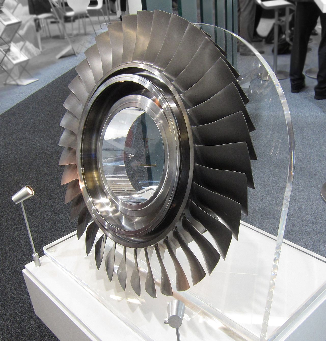
Compression happens in stages, not all at once. Trying to compress all the air at once would stall the flow and shut the engine down. A compressor consists of a series of rotating blades (rotors) alternating with stationary vanes (stators). Each pair of rotors and stators adds a small pressure increase. Together, dozens of these stages multiply the pressure dramatically.
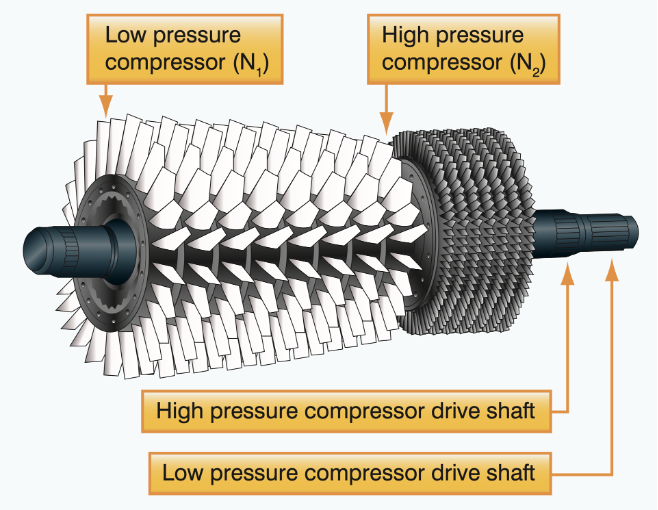
A modern turbofan has 2 distinct compressor sections:
This design lets the LPC spin slower (at a similar speed to the fan) while the HPC spins faster for peak efficiency, enabling overall PRs of 40:1 to 50:1.
If you also consider the increase in pressure provided by the huge fan in modern turbojet engines, the overall increase in pressure between the air entering the engine and that entering the combustion chamber is even greater. This is called the overall compression ratio (OCR). The GE9X boasts an OCR of 60:1 with a compressor PR of 27:1.
Take a closer look at a real life jet engine compressor in action.
Increasing the PR sounds simple – just add more stages and make the blades spin faster. However, as we have come to expect, this is no free lunch. Each increase introduces new problems.
But engineers don’t maximize compression blindly. At some point, adding more stages adds too much weight, more intricate blade designs with tighter tolerances raise costs and complexity, and higher temperatures reduce component durability. Therefore, the best design is not actually the highest PR design - it’s the optimum PR design.
The tips of the high-pressure compressor blades in many GE Aerospace engines travel faster than sound. For example, the blade tips in the GE90 compressor travel at between Mach 1.2 and Mach 1.6. The speed of sound is Mach 1.
GE Aerospace engineers have developed many ingenious ways of producing compressor blades able to withstand the enormous pressures, high temperatures, and punishing mechanical stresses that come with ever greater PRs.
Instead of making the rotors as a central hub with many attached blades, rotors are made as blisks. “Blisk” is a portmanteau of "blade" and "disk" and is a rotor disk and blade machined out of a single piece of material.
The benefits of blisks include weight savings (there is no need for blade attachments), improved aerodynamics (there are no gaps between the blades and the hub), and better reliability (there is far less chance of a blade detaching). But there is a trade-off. If one blade is damaged, the entire blisk may need to be replaced.
One of the clear downsides of blisks is that if one blade gets damaged it can be hard to just replace that one blade. But linear friction welding makes this possible.
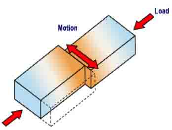
This is a technique of fusing 2 pieces of metal by pushing them together very firmly and then vibrating one of the pieces to create friction and heat. This causes the pieces to fuse without melting and avoids the defects that melting produces.
See how a blisk is machined out of a single piece of titanium.
Secondly, engines like the GEnx, have compressor blades of titanium aluminide (TiAl). TiAl has several advantages over traditional titanium alloys. It is lighter (4 g/cm3 vs 4.5 g/cm3), more heat-resistant (up to 800°C vs about 550°C), stiffer and reacts less with oxygen and nitrogen at high temperatures, meaning that the compressor can run faster for improved PRs.
However, titanium aluminides are more brittle than traditional titanium alloys and need more complex and expensive manufacturing techniques.
Read the article The Evolution of Compressor Blades: From Steel to Titanium to Ceramic Composites to learn more.
Titanium aluminides are classified as ordered intermetallic compounds, which means they form when atoms of two or more metals (in this case titanium and aluminium) combine in a fixed ratio to produce a crystalline material with a different structure than either of the individual metals.
As we have seen increasing the PR in a jet engine improves fuel efficiency and boosts overall engine performance. But this comes at the expense of increased heat, mechanical stress, and expensive manufacturing and operational complexity. Each extra unit of compression delivers diminishing returns. An engine that is slightly less efficient but significantly more durable can still save airlines millions of dollars over its lifetime.
In the next article, we’ll move to the hottest part of the engine where engineers push combustion temperatures far beyond what materials should be able to tolerate but find ways to make them survive anyway.