

Extreme Machine
Extreme Machine Part 2: Must Move More Air
Nerd Out


We noted in Part 1 that turbofans are very efficient jet engines and that the greater the bypass ratio, or BPR (the ratio of air bypassing the core to that going through the core), the more efficient and powerful the engine becomes. So, if increasing the BPR increases the engine efficiency and power, and increasing the engine size increases the BPR, engineers should just keep making bigger and bigger engines, right? Well, they have and they do, to a point!
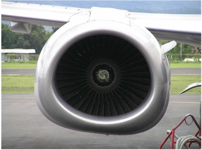
If you look at a modern turbofan engine and an older one side by side, the difference is obvious. Modern engines are enormous and have enormous fans, creating bypass ratios of 10:1 to 12:1. Some experimental ultra-high bypass designs are aiming at ratios of 15:1 to 17:1.
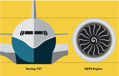
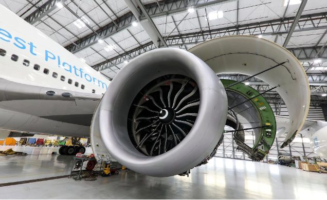
The GE9X from GE Aerospace, for example, has a fan diameter of 3.4 m (over 11ft), making it the largest (and most powerful) commercial aircraft engine ever.
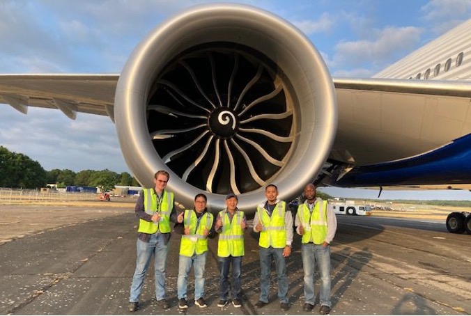
The GE9X engine on the Boeing 777 is bigger than the Boeing 737 fuselage! The GE9X engine is also 4 times more powerful than those typically on the 737.
To dive deeper into the GE9X engine, watch these videos:
Take a detailed look at the fan, compressor, combustor and materials technologies that make the new GE9X the most fuel-efficient engine GE has ever produced
Take a tour through the world's biggest jet engine - the GE9X - which powers the Boeing 777x and Boeing 747.
The GE9X is capable of generating a record breaking 134,000 pounds of thrust, whipping up a miniature Category 5 hurricane in its wake.
Learn how the GE9X will revolutionize the industry.
We know that increasing the BPR increases the engine’s efficiency, but why is this the case? To produce thrust, an engine must push air backwards. There are basically two ways to do this:
It turns out that the second option is more efficient. Pushing lots of air gently wastes far less energy than blasting a small jet of air at high speed. This results in lower fuel burn, lower exhaust velocity, and less noise and is why modern turbofans are far more efficient than early jet engines.
We can explain why the second option is more energy efficient by looking at the physics. Stay with me here.
Changing an object’s motion (like moving a jet engine and aircraft forward) requires a change in that object’s momentum. Momentum (p) is given by
\[ p=mv \]
where
\[ m=\text{the mass of the object}\]
\[ v=\text{the velocity of the object}\]
Impulse, $ \text{J} $, is defined as the change in momentum (e.g., making an object move faster). Therefore, impulse is given by
\[ J=m \times \Delta v \]
where
\[ \Delta v=\text{the change in the velocity of the object} \]
If we doubled the mass and halved the change in velocity, we would still achieve the same impulse.
\[ J=2m \times \left( \frac{1}{2}\Delta v \right) \]
Now kinetic energy is given as
\[ E_k=\frac{1}{2} m\Delta v^2 \]
If we substitute our new mass $ \left( 2m \right) $ and new change in velocity $ \left( \frac{1}{2} \Delta v \right) $ into this equation, we get
\[ E_k = \frac{1}{2}(2m)\left( \frac{1}{2} \Delta v \right)^2 = \frac{1}{4}m \Delta v^2 \]
What if we halved the mass and doubled the change in velocity to achieve the same impulse?
\[ J=\frac{1}{2}m \times 2 \Delta v \]
If we substitute our new mass $ \left( \frac{1}{2}m\right) $ and new change in velocity $ (2 \Delta v) $ into the kinetic energy equation, we get
\[ E_k = \frac{1}{2} \left( \frac{1}{2}m) \right) \left( 2 \Delta v \right)^2 = m \Delta v^2 \]
We can see that doubling the mass and halving the change in velocity lets us achieve the same impulse (or change in momentum) for a quarter of the energy than if we halved the mass and doubled the change in velocity. For our jet engine, that means pushing twice as much air half as fast is four times more energy efficient than pushing half as much air twice as fast.
To learn more about why engineers are always striving to make bigger engines watch this video.
As much as increasing engine size to increase the bypass ratio sounds like a great idea, making bigger engines with bigger fans comes with costs and creates all sorts of engineering problems, some of them extreme.
There are four primary trade-offs that need to be managed when trying to increase the size of turbofan engines and their fans.
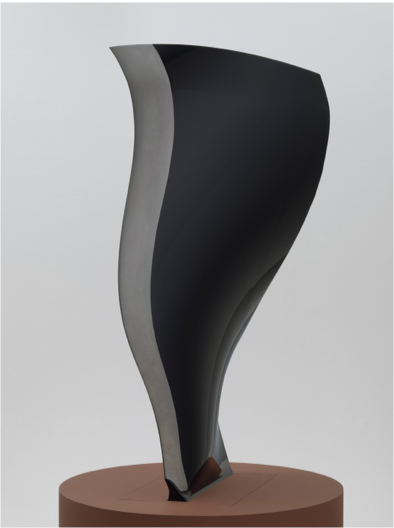
The fan blades from the GE90 engine are so beautifully designed and manufactured that one of them is part of the New York Museum of Modern Art’s collection.
The force experienced by a spinning object like a fan blade (called the centripetal force) is given by
\[F=m\omega^2r \]
where
\[ m = \text{mass of the object} \]
\[ \omega = \text{angular velocity (the speed of rotation)} \]
\[ r = \text{radius or distance of the object from the center of rotation} \]
Larger fans require larger blades. This increases the value of r and therefore the centripetal force. Making blades stronger usually means making them thicker. This increases their mass $(m)$, again increasing the force. So, we need to slow the spinning $(\omega)$, but this reduces the amount of bypass airflow, defeating the reason for the bigger fan in the first place.
As the centripetal force increases, we also need a stronger fan hub and a thicker, stronger engine casing to contain the bigger blades if one ever breaks apart. This all adds more material and hence, more mass. More mass reduces aircraft performance and increases costs.
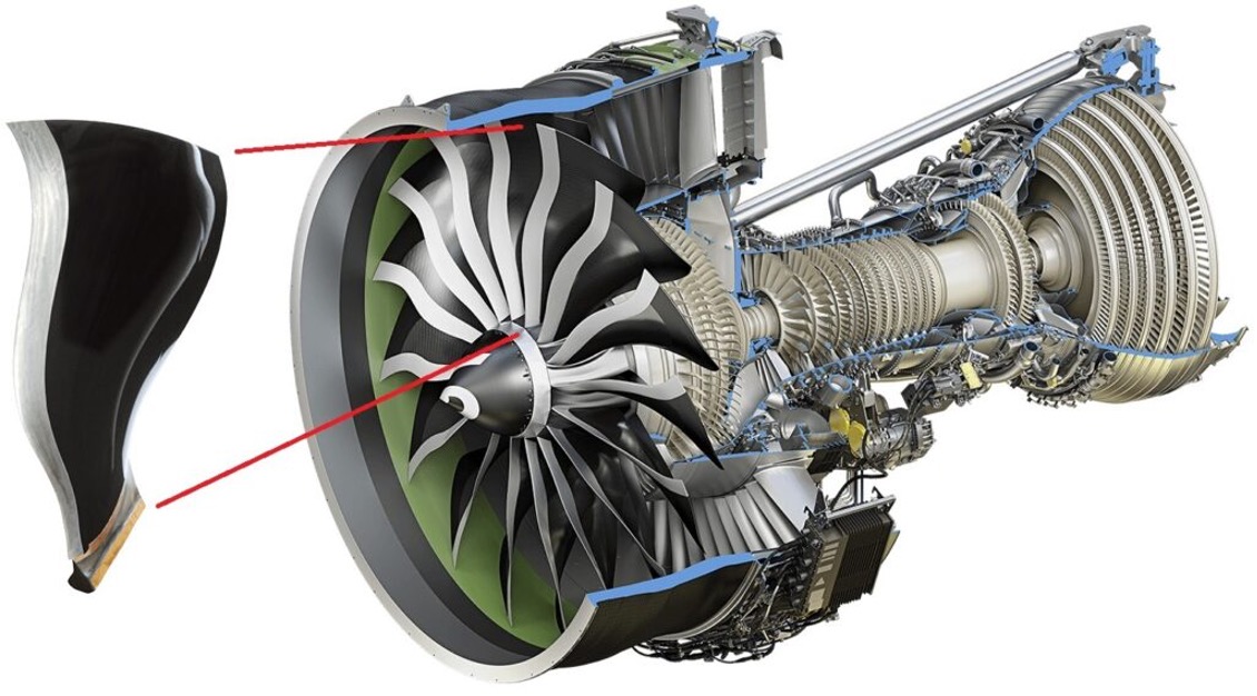
GE Aerospace engineers addressed this by making the blades much stronger but also lighter and thinner by manufacturing them out of carbon-fiber composite. Each blade is made from about 1,700 sheets of carbon fiber impregnated with a very strong and durable resin and then cured at high temperature and pressure.
We use \[ F_c=m\omega^2r \] to calculate centripetal force. A GE9X fan has a radius of 1.7 m, spins at 2,510 RPM at take-off, with each blade weighing about 25 kg. This means that each blade experiences a centripetal force of about 2,900,000 N. That is equivalent to the weight of a Boeing 747! On each one of the 16 blades!
Learn more about these carbon-fiber composite fan blades.
Watch how they test these blades to make sure they can withstand the enormous stresses they are routinely placed under as well as incidents like bird strikes.
A bigger engine with a bigger fan is a wider engine, which creates more aerodynamic drag. Increased drag increases fuel burn.
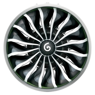
GE Aerospace engineers addressed the problem of drag in 2 ways. Firstly, they redesigned the fan blades using advanced 3D modelling to have a complicated 3D swept shape. This improved the aerodynamics and operation of the blades. This also allowed them to successively reduce the number of blades in newer engines.
Having fewer blades with the swept design reduces drag and weight. This improves the airflow and reduces overall turbulence, so each blade processes more air with less waste. It also lowers the “aerodynamic interference” between adjacent blades, enabling wider spacing without losing efficiency and allows the fan to spin faster and move air more quickly without the normal energy costs.
Secondly, they also carefully designed the nacelle (the engine’s outer casing). This included manufacturing it out of lighter and stronger composite materials and redesigning the lip to reduce drag and improve airflow into the engine.
GE Aerospace engineers have used fewer and fewer fan blades in their commercial jet engines over the years.
Large fans need enormous torque, or turning force, to make them spin. This energy needs to be generated by the turbine. The more energy used to turn the fan, the more fuel needs to be burnt, or the less energy is available to the rest of the engine or for thrust. This increased torque also adds stress to shafts, bearings, and gears.
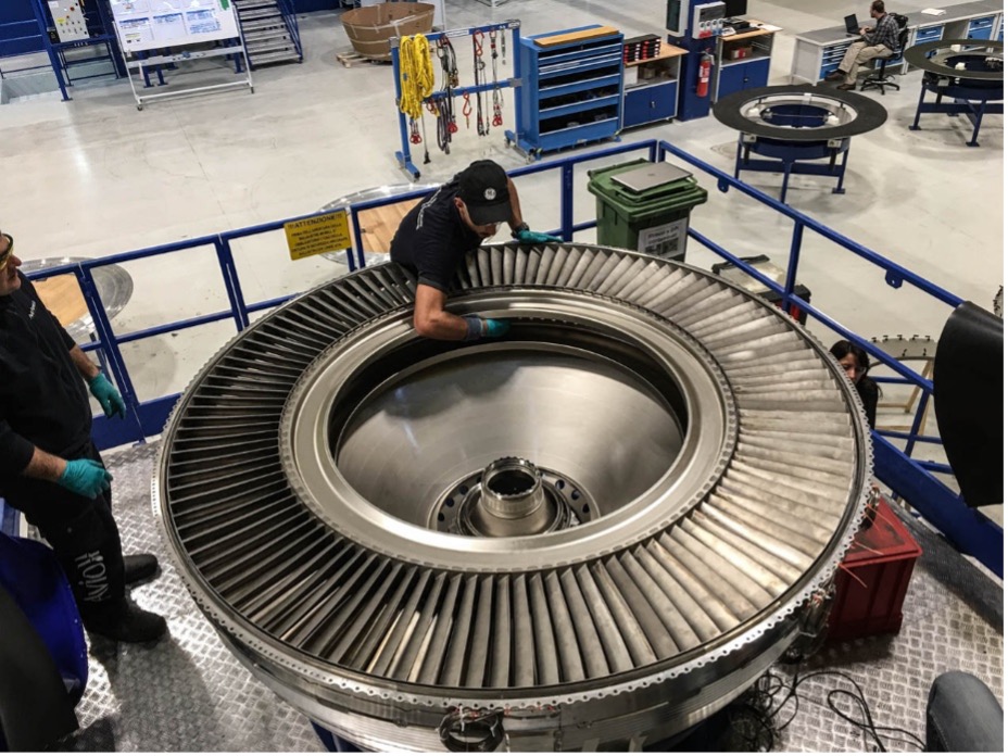
GE Aerospace engineers addressed this challenge by designing a highly efficient 3-stage low pressure turbine for the GE9X. Reducing the number and mass of the fan blades also helps to reduce the torque required.
Watch this video to learn more about this low pressure turbine.
Each of the 16 fan blades in the GE9X can cost up to US$100,000 to make.
Bigger engines create integration problems with the aircraft they are design to propel. Ground clearance limits how large engines can be. Wings must be redesigned to carry heavier engines. Airports and maintenance equipment must adapt.
GE Aerospace engineers dealt with this challenge by mounting the engine forward and higher on the wing. With the GE9X, they also tilted the front of the engine up by 7 degrees. Boeing also made the landing gear of the 777X taller.
Engine design does not happen in isolation—it affects the entire aircraft.
The CFM56 engine used on the Boeing 737-400 has a very distinctive flattened bottom to create the needed ground clearance, earning it the nickname of the “hamster pouch”.
GE Aerospace engines like the GE90, GEnx, and GE9X pushed bypass ratios higher with each generation, but never blindly. Increasing the bypass ratio improves fuel efficiency, increases thrust and performance, and reduces noise. But it also increases size, weight, and complexity and raises manufacturing and maintenance costs.
Therefore, each design decision reflects careful choices about:
There is no single “best” bypass ratio – only the best compromise for a given aircraft and mission. A slightly smaller fan that lasts longer and costs less may be a better engineering solution than the biggest possible fan.
One of the hardest skills in engineering is knowing when to stop, when not to optimize further. The goal cannot simply be the highest bypass ratio. The goal must be the best overall system for the given circumstance.
In the next article, we’ll move from the outside of the engine to the first part of the core to discover how engineers compress the air to extreme pressures.