

Extreme Machine
Extreme Machine Part 4: Getting Hotter
Nerd Out


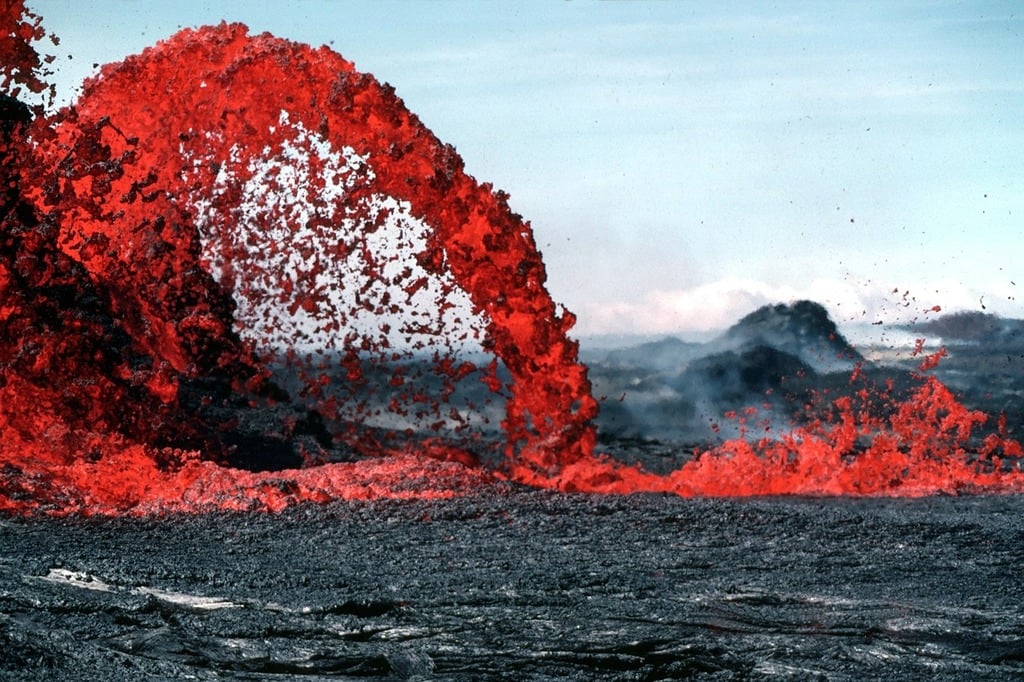
If compression is about squeezing air harder, combustion is about making it hotter. The combustion chambers of modern jet engines are some of the most extreme environments we have ever engineered. They operate at temperatures hotter than molten lava – hotter, in fact, than the melting point of many of the metals inside them.
That sounds impossible. It isn’t. But it does require some of the most extreme engineering on Earth.
But why is hotter better? Well, the temperature at which fuel burns inside a jet engine (the turbine inlet temperature) is one of the strongest drivers of engine efficiency. Higher combustion temperatures mean that:
This simply means that hotter engines are more efficient engines. But making hotter engines is anything but simple.
Modern turbofan engines operate at combustion temperatures above 1,600°C. This is hotter than the melting point of rock. It’s even hotter than the melting point of stainless steel.
Although burning fuel sounds like it should be really simple, combustion is one of the most delicate and constrained engineering problems in the entire engine. In the combustor, the high-pressure air from the compressor burns with the injected fuel to produce a high-volume combustion gas that drives the turbines. The gas ultimately exits out the back of the engine and produces jet thrust.
Therefore, the combustor’s job is to:
This must all be done:
The Carnot efficiency limit is a concept in thermodynamics that describes how temperature affects the efficiency of any heat engine (like a jet engine).
The maximum theoretical efficiency is given as:
\[ \eta_{carnot} = 1 - \frac{T_C}{T_H} \]
Where $ T_C $ and $ T_H $ are the temperatures (in Kelvin) of the cold and hot reservoirs respectively. The greater the difference, the more energy (and work) can be extracted.
Therefore, combustion sits at the intersection of three competing goals:
You can’t maximize all three at once. You need combustion to be as stable and efficient as possible while also being close to stochiometric levels (that is, where all the oxygen is combined with all the fuel’s carbon) at all engine power levels, altitudes, and speeds. It must also meet ever tighter emissions standards and deliver ever higher levels of heated gas in the smallest possible volumes to keep engine mass and size low. These complexities have made combustor design a real “rocket science.”
Reactants are at stoichiometric levels when mixed in the exact ratio dictated by the balanced chemical equation of the reaction. In this case, if the reaction proceeds to completion, all the reactants will be completely consumed leaving no excess or leftovers.
It's like cooking just enough of every dish at a dinner party that everyone eats all they want and you have no leftovers!
Modern turbofan engines operate with a much leaner total air-to-fuel ratio than car engines. Overall air-to-fuel ratios typically range from 40:1 to 80:1 by weight. However, the actual combustion in the primary flame zone occurs at a much richer ratio, roughly 15:1. This is because much of the air entering the engine core is used for cooling and to dilute the combustion gas.
Getting this mix of fuel and compressed air just right is the core problem engineers need to solve in the combustor. Jet fuel does not burn efficiently unless it is finely atomized, evenly mixed with the air, and held in the right temperature and pressure range.
If the mixture is too rich (too much fuel) soot and NOx emissions increase, and local hot spots can form. A mixture which is too lean (too much air) can cause flame instability or even flameout.
So, combustors carefully control where and how much fuel is mixed with the compressed air.
Below is an image of an older type of combustor called a tube combustor because it helps illustrate how the compressed air is directed and used by the combustor.
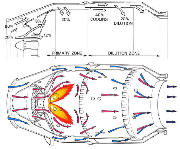
In many engines, less than 30% of the air entering the combustor is used directly for burning fuel. The rest is used for cooling and dilution.
Dilution happens when compressed air that has not be combusted is mixed with combustion gasses to cool it down, even out the temperature, and reduce NOx formation.
We can see how the combustor is designed to direct only a small proportion (20%) of the air to the flame region to be burnt at more than 2,000°C in the primary zone. About half of the remaining air is then directed into the dilution zone to cool the combustion gasses to about 1,600°C to 1,800°C. Without reducing the turbine inlet temperature, the turbine blades would melt.
To create a more efficient combustor with smaller dimensions and more uniform turbine inlet temperatures, the annular combustor was invented and is mostly used today. It consists of a ring of smaller combustor units. The image below shows the latest combustor design developed for the GE9X.

If you want to dive deep into the ins and outs of combustion, then the video below is for you.
One of the biggest combustion challenges is controlling nitrogen oxides (NOx). NOx forms when combustion temperatures are very high and nitrogen and oxygen in the air react together. So, while hotter combustion improves efficiency, it also dramatically increases NOx emissions.
Modern engines increasingly use lean-burn combustors, which pre-mix fuel with a larger volume of air and operate with lower peak flame temperatures to reduce NOx formation.
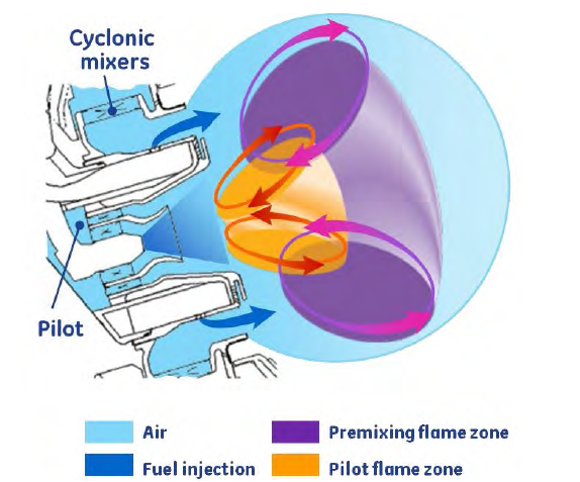
But lean combustion is harder to control. The flames are less stable, ignition is more difficult, and there is a greater risk of uneven burning. This requires tighter tolerances and more innovative and complex designs to solve. One such innovative design is GE’s Twin Annular Pre-mixing Swirler or TAPS combustor, now in its third generation in the GE9X engine.
This combustor uses a fuel injector (see image below) that divides the fuel and airflow into a Pilot (orange) and Main (purple) flame area and cyclonic mixers that ensure optimal mixing of the fuel and air.
At engine start and low-power, only the rich-burn Pilot part is in operation. At higher power, the lean-burn Main outer ring of air and fuel cut in and dominate.
In total, about 70% of the combustor air passes through the Pilot and Main parts, where the dominant Main part makes the whole combustor a lean combustor with low emissions at normal operating power. By keeping the flame zone short with low top temperatures, the design delivers 60% fewer NOx emissions.
NOx is a shorthand for 2 types of nitrogen oxide – NO and NO2. Both are a natural by-product of combustion, and both can have severe environmental effects.
Also, as we know, air entering the combustor is highly compressed and moving extremely fast. If left unchecked, it would simply blow the flame out. Combustors like the TAPS solve this by creating these recirculation zones that slow the airflow locally and help anchor the flame in place.
Further, the turbine blades are already at their thermal limits. They cannot handle hot streaks, uneven temperature profiles, or sudden fluctuations. So, modern combustors like TAPS also include dilution as described above.
The combustor is not optimized for maximum heat. It is optimized for the maximum acceptable heat, cleanly and evenly delivered.
The main trade-offs being managed are:
The combustor does not set the engine’s limits alone. It hands its work to the turbine which must survive whatever heat, pressure, and flow the combustor produces. This is where things get really interesting and where the real constraints appear.
In the next article, we’ll look at that part of the engine that extracts as much of the energy released by combustion as possible and, in doing so, seems to break the laws of physics.